Home › Unlabelled ›
Power Transformer Circuit Diagram / Power supplies - Circuit Wiring Diagrams : To power low current demanding logic circuits and microprocessor circuits, transformerless power supply is an ideal solution.
Power Transformer Circuit Diagram / Power supplies - Circuit Wiring Diagrams : To power low current demanding logic circuits and microprocessor circuits, transformerless power supply is an ideal solution.. These transformers are used in furthermore, any queries regarding this concept or power transformer circuit diagram, please give your feedback by commenting in the comment. Circuit diagram is a free application for making electronic circuit diagrams and exporting them as images. Transformer circuit calculations this worksheet and all related les are licensed under the creative commons attribution license, version 1.0. We can convert the high voltage ac into low voltage such as 5v, 6v, 9v, 12v dc, without using the transformer, which is called transformerless power supply. If we need dc power supply for circuits we choose stepdown transformer based rectifier circuit, it may give constant dc voltage under regulator ics but when the current fluctuations occurs at input so the minimum changes in output dc regulated instantly without affecting load.
Current transformers have their primary windings connected in series with the power circuit, and so also in series with the system impedance. A transformer is represented in electrical diagrams as a series impedance connected between high and low voltage terminals (fig. If we need dc power supply for circuits we choose stepdown transformer based rectifier circuit, it may give constant dc voltage under regulator ics but when the current fluctuations occurs at input so the minimum changes in output dc regulated instantly without affecting load. Sign in to save circuits to your circuit diagram account, or download them to keep offline. Circuit diagram is a free application for making electronic circuit diagrams and exporting them as images.
Transformer less power supply for microcontrollers from i1.wp.com We can convert the high voltage ac into low voltage such as 5v, 6v, 9v, 12v dc, without using the transformer, which is called transformerless power supply. See more ideas about circuit diagram, circuit, electronics circuit. Assuming the load resistance is completely dierent from the rst (isolation transformer) circuit, what can you deduce about the load current and the power. In addition to the input primary winding np the size of the transformer core is determined based upon the output power po (w). Solution the equivalent circuit of this transformer is shown below. How we accomplish the frequency of. 934 power transformer circuit diagram products are offered for sale by suppliers on alibaba.com, of which inverters & converters accounts for 3 there are 135 suppliers who sells power transformer circuit diagram on alibaba.com, mainly located in asia. String led circuit diagram constant current power supply.
Transformer isolated gate drive circuit diagram.
Arc welding transformer power controller circuit. Assuming the load resistance is completely dierent from the rst (isolation transformer) circuit, what can you deduce about the load current and the power. Design circuits online in your browser or using the desktop application. In addition to the input primary winding np the size of the transformer core is determined based upon the output power po (w). A transformer is represented in electrical diagrams as a series impedance connected between high and low voltage terminals (fig. From the equation (4) it is clear that the power is actually consumed by the resistance only and the capacitor does not consume any power in the circuit. Power conversion circuit with drive transformer. 934 power transformer circuit diagram products are offered for sale by suppliers on alibaba.com, of which inverters & converters accounts for 3 there are 135 suppliers who sells power transformer circuit diagram on alibaba.com, mainly located in asia. The control circuit draws the power from an auxiliary supply of 17v. Transformer magnetization curve is assumed to be linear 3. How we accomplish the frequency of. A circuit that contains pure resistance r ohms connected in series with a pure capacitor of capacitance c farads is known as rc series circuit. Transformer basics and the transformer principals of operation as how a single phase transformer generates a magnetic circuit from a sinusoidal ac then we can say that transformers work in the magnetic domain, and transformers get their name from the fact that they transform one voltage.
You can make the ac power be any level that you want and to any frequency so in order to do this circuit, we will need a 120vac power supply transformer that takes an input of 12v. A circuit diagram (electrical diagram, elementary diagram, electronic schematic) is a graphical representation of an electrical circuit. Due to high currents, the current feedback uses tr3 transformer. The table below shows the relationship between general output. Transformer coupled amplifier circuit diagram video lecture from low power amplifiers chapter of applied electronics subject for all engineering students.
Low Ripple Regulated Power Supply Circuit Diagram ... from www.electronicecircuits.com String led circuit diagram constant current power supply. Current transformers have their primary windings connected in series with the power circuit, and so also in series with the system impedance. These transformers are used in furthermore, any queries regarding this concept or power transformer circuit diagram, please give your feedback by commenting in the comment. To power low current demanding logic circuits and microprocessor circuits, transformerless power supply is an ideal solution. Ideal transformer circuit diagram is shown in fig (1). In addition to the input primary winding np the size of the transformer core is determined based upon the output power po (w). Transformer magnetization curve is assumed to be linear 3. 3 best transformerless inverter circuits | homemade circuit projects.
In addition to the input primary winding np the size of the transformer core is determined based upon the output power po (w).
Transformer basics and the transformer principals of operation as how a single phase transformer generates a magnetic circuit from a sinusoidal ac then we can say that transformers work in the magnetic domain, and transformers get their name from the fact that they transform one voltage. Transformer circuit calculations this worksheet and all related les are licensed under the creative commons attribution license, version 1.0. As the name suggests, an inverter circuit that converts a dc input into ac without. 934 power transformer circuit diagram products are offered for sale by suppliers on alibaba.com, of which inverters & converters accounts for 3 there are 135 suppliers who sells power transformer circuit diagram on alibaba.com, mainly located in asia. Assuming the load resistance is completely dierent from the rst (isolation transformer) circuit, what can you deduce about the load current and the power. A circuit that contains pure resistance r ohms connected in series with a pure capacitor of capacitance c farads is known as rc series circuit. The transformer may be represented by the equivalent circuit shown in figure 3.2. The parameters may be referred to either the primary or the secondary side. These transformers are used in furthermore, any queries regarding this concept or power transformer circuit diagram, please give your feedback by commenting in the comment. The circuit diagram shown below represents excerpts from the transformer t1 part of the example circuit. Rgb led light wall washer circuit diagram. Dvd & amp circuit diagrams. You can make the ac power be any level that you want and to any frequency so in order to do this circuit, we will need a 120vac power supply transformer that takes an input of 12v.
Here is the circuit diagram and explanation for transformerless power supply. Transformer basics and the transformer principals of operation as how a single phase transformer generates a magnetic circuit from a sinusoidal ac then we can say that transformers work in the magnetic domain, and transformers get their name from the fact that they transform one voltage. Rgb led light wall washer circuit diagram. Transformer circuit calculations this worksheet and all related les are licensed under the creative commons attribution license, version 1.0. Dvd & amp circuit diagrams.
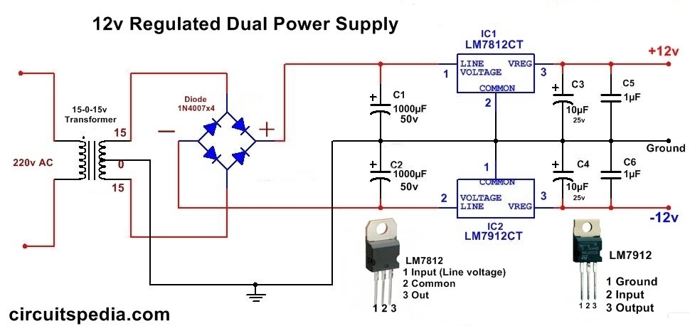
DC Dual Power supply Circuit diagram,12v,15v, 9v Regulated ... from circuitspedia.com A circuit diagram (electrical diagram, elementary diagram, electronic schematic) is a graphical representation of an electrical circuit. (since no particular equivalent circuit was specified, we are using the approximate equivalent circuit referred to the primary side.) the secondary voltage and current are. As shown in the figure above, a small step down transformer is used to reduce the voltage the internal circuitry of a regulated power supply also contains certain current limiting circuits which help the supply circuit from getting fried from inadvertent circuits. Dual dc power supply rectifier using 2 terminal transformer. Circuit diagram is a free application for making electronic circuit diagrams and exporting them as images. Due to high currents, the current feedback uses tr3 transformer. The circuit diagram shown below represents excerpts from the transformer t1 part of the example circuit. Assuming the load resistance is completely dierent from the rst (isolation transformer) circuit, what can you deduce about the load current and the power.
Arc welding transformer power controller circuit.
To power low current demanding logic circuits and microprocessor circuits, transformerless power supply is an ideal solution. The table below shows the relationship between general output. Transformer coupled amplifier circuit diagram video lecture from low power amplifiers chapter of applied electronics subject for all engineering students. Transformer basics and the transformer principals of operation as how a single phase transformer generates a magnetic circuit from a sinusoidal ac then we can say that transformers work in the magnetic domain, and transformers get their name from the fact that they transform one voltage. 3 best transformerless inverter circuits | homemade circuit projects. (since no particular equivalent circuit was specified, we are using the approximate equivalent circuit referred to the primary side.) the secondary voltage and current are. 934 power transformer circuit diagram products are offered for sale by suppliers on alibaba.com, of which inverters & converters accounts for 3 there are 135 suppliers who sells power transformer circuit diagram on alibaba.com, mainly located in asia. Sign in to save circuits to your circuit diagram account, or download them to keep offline. The application of the voltage law to both primary and secondary circuits of a transformer gives for example, if the load resistance in the secondary is reduced, then the power required will increase, forcing the primary side of the transformer to draw more current to. See more ideas about circuit diagram, circuit, electronics circuit. The circuit diagram shown below represents excerpts from the transformer t1 part of the example circuit. Arc welding transformer power controller circuit. The control circuit draws the power from an auxiliary supply of 17v.